RuggedPax Companion for Paxton NET2
RuggedPax Companion for Paxton NET2
RuggedPax Companion
NEW ITEM. Added 11-26-24!
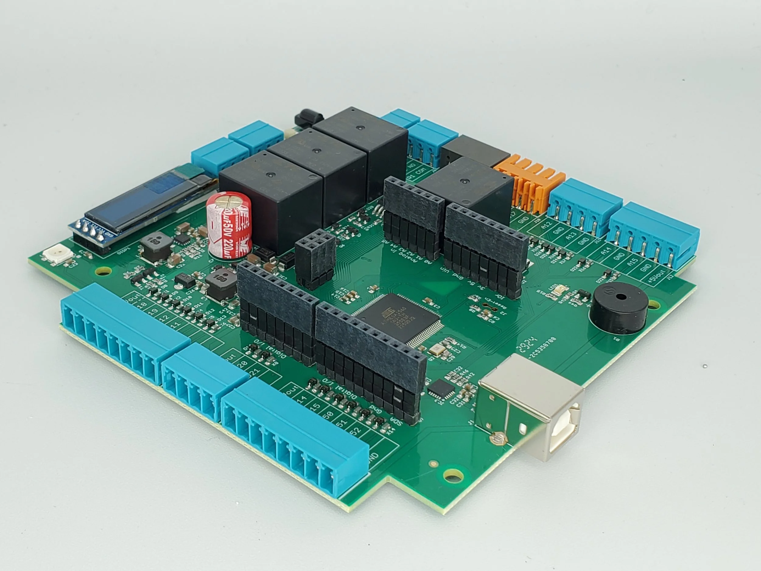
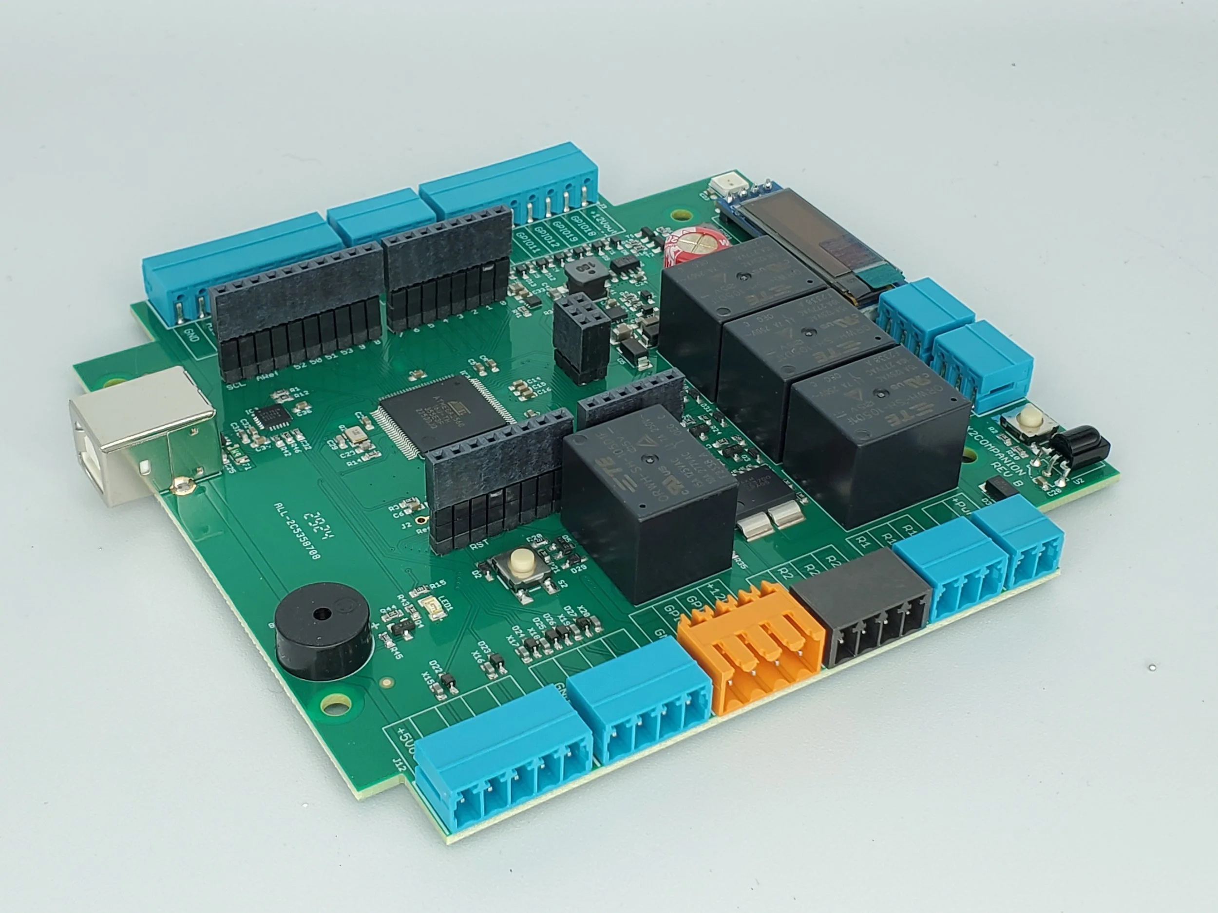
The RuggedPax Companion can be used two ways- true to its namesake as a companion or independently. As a companion it supplements the popular Paxton NET2 platform adding even more features, conveniences, and Rugged Protection not available at the OEM level. As an independent the Companion board can be used as a stand alone Arduino-based custom access control board. Purpose-built through our custom design program the Companion provides greater flexibility and control by supplementing or replacing NET2 offerings. The RuggedPax Companion instantly provides a professional commercially installable solution for the reasons below.
Unlock New Possibilities with the Arduino Ecosystem
Even if you're not using the Paxton NET2 system, our Arduino-based Companion board offers a robust platform for building custom access control solutions. With full compatibility with the popular Arduino IDE, you’ll have access to a world of programming flexibility and community support, enabling you to design systems tailored to your unique needs.
Designed to Fit Seamlessly into Paxton NET2-compatible Enclosures
Take advantage of the existing infrastructure of NET2-compatible enclosures, such as the versatile Trove from Altronix, which can house up to 8 NET2 units along with power supplies. The Companion board fits perfectly in these enclosures, whether you need it to stack underneath a NET2 unit using the provided standoffs or to operate without a NET2 unit altogether. This means you can pair your custom system with high-quality, off-the-shelf hardware for a professional finish. https://www.altronix.com/products/Trove2PX2
Create a Scalable Solution
From a single-door access point to a multi-door networked system, the Companion board scales with your requirements. Harness the power of Arduino’s ecosystem to integrate sensors, locks, and communication protocols, while leveraging the proven reliability and capacity of NET2-compatible products for your enterprise integration, power and mounting needs.
Files, downloads, pictures, and more are available on GitHub:https://github.com/chipguyhere/RuggedPaxCompanion
What is the board?
The Companion board discreetly installs behind a Paxton Net2 Access Control Unit (ACU), fitting completely inside the original Paxton cabinet. The Companion performs additional custom functions not available in the stock Net2 system. These functions are of your choosing from this stock firmware image, or one that you customized and loaded yourself since the board is 100% compatible with the Arduino IDE development environment.
Viewed another way, Companion is an Arduino board that can be used to implement a customized security solution, which supports having a Paxton Net2 Access Control Unit placed on top of it. This effectively "grafts in" an industry-leading solution and an established enterprise software/vendor ecosystem that serves as a solid starting point for your custom door installation. Furthermore a commercial rated UL-listed single enclosure (https://www.altronix.com/products/Trove2PX2) exists from Altronix for qty 8 to 12 of this board shape with a suitable power supply. Essentially this is also a commercially installable “Rugged Arduino Mega” with immediate benefit for someone not necessarily buying it to enhance a Paxton install but rather one wishing to stay in the Arduino environment.
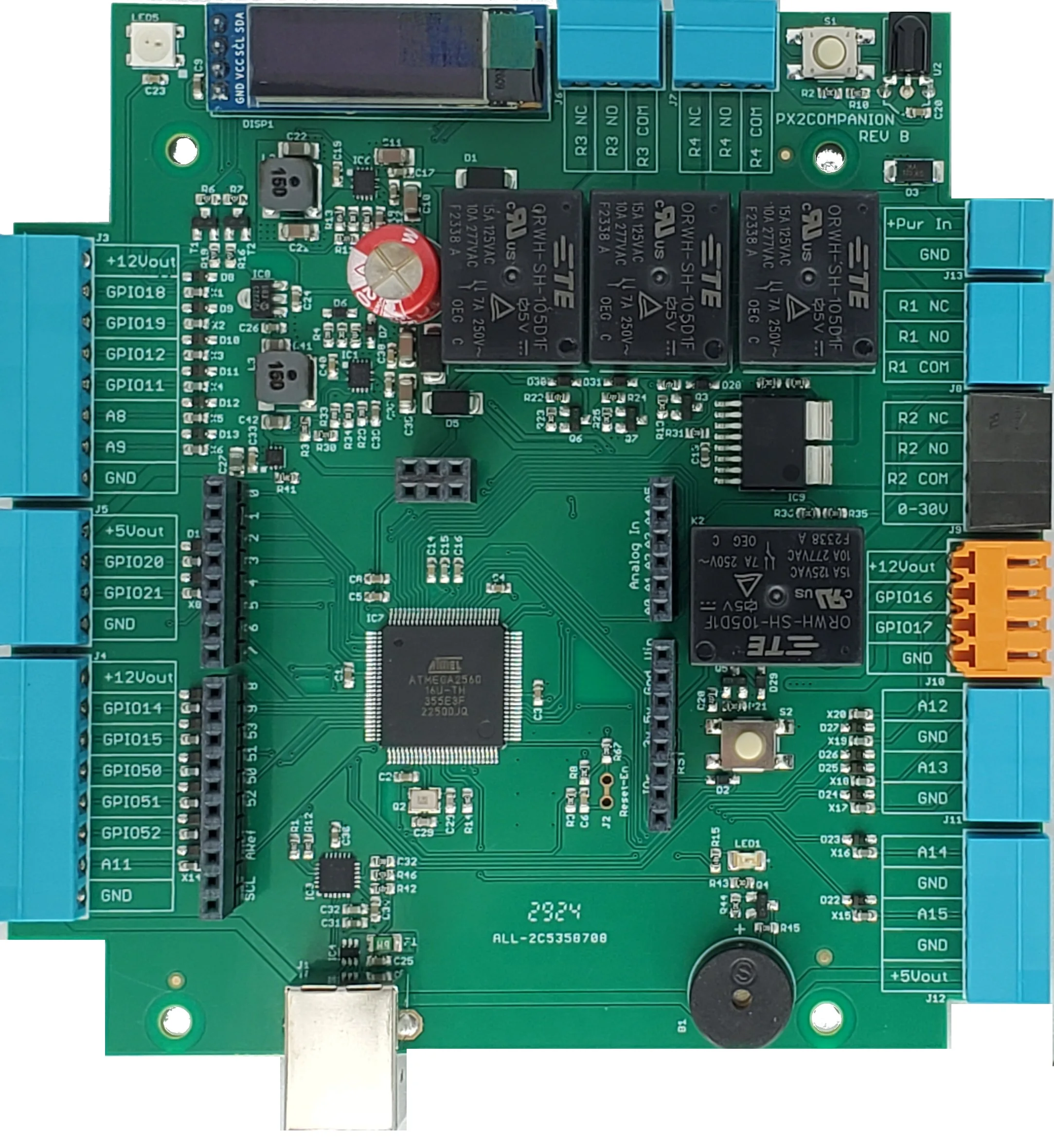
Hardware Features of the Ruggeduino Companion board
Fits perfectly behind a Paxton Net2 ACU in its native enclosure, using standard 1-inch nylon standoffs
Atmega2560 Arduino-compatible processor
Overvoltage protection for external-facing pins
Arduino Shield-compatible connector
4 programmable relays
Current sensor on flow through Relay1
128x32 OLED display
Eye sensor for IR remotes (configurator)
Supply voltage 6 to 30 volts
Onboard current-limited 12-volt power supply (1 amp)
Onboard current-limited 5-volt power supply (1 amp)
Beeper, RGB status LED, and setup button
Some Firmware Features
Use generic Wiegand-compatible RFID card readers and PIN keypads, with support for variable bit lengths (e.g. for HID MultiClass and similar readers) and proper numeric conversion of Paxton-branded tokens (so they read the same code as on Paxton readers). This firmware emulates the clock-and-data protocol used by Paxton's own card readers and keypads, so, you'll simply program them as "Paxton Reader" with "Paxton Tokens".
Multiple relay outs. Switch multiple loads (up to 4 relays) when access is granted.
Current (amperage) sensor, as a way of detecting lock status. Can be used to drive a relay out and inform a security system.
Motion detector timing program. Avoids allowing the motion detector to unlock the door for the first 20 seconds of being closed, so it locks immediately upon closure and allows the person closing the door to verify it's closed, without the motion detector immediately unlocking it as they try to walk away.
Door-left-open warning beep (for RFID keypads with a beep function)
Two door contact inputs, and logic for handling double-doors (i.e. single doors that have two slabs)
Use any regular dry-contact doorbell switch to transmit the "doorbell pressed" message to the Paxton Net2 ACU.
Switch auxiliary loads (such as building lights) with unused RFID keypad keys (e.g. star key on RFID keypad switches a relay for 1-99 seconds). Customize the keys or logic by editing the source code.
The ability to use the free Arduino IDE software to make modifications to the firmware (or create your own) with intermediate-level Arduino programming experience
Other features in the concept and development stage include support for a privacy toggle switch (to allow occupants to select a mode where card swipes go to the Reader 2 port, separately configurable in Paxton to have different access rules), and a serial logger/uplink connection to enable more options for integration with a security/alarm system.
Installing in a Paxton ACU cabinet
Open your Paxton cabinet. You'll find the Paxton ACU board attaches to the cabinet via a mounting plate and four plastic snap-in standoffs. Remove the mounting plate (held in by a screw), and then remove these standoffs from the ACU board and the mounting plate (which may require carefully squeezing them with needle-nose pliers). These standoffs will not be needed and can either be saved or discarded.
Attach the four supplied brass #6-32 standoffs to the mounting plate (where you removed the original standoffs), and secure these in place with the metal nuts provided. The nuts go on the back side, facing the wall, so the threaded side faces you when the mounting plate goes back into the cabinet.
Re-attach the mounting plate into the Paxton cabinet.
Hold the Companion board onto the mounting plate, lining up the holes in the Companion board with the brass standoffs.
Use the four white plastic standoffs (provided) to mount the Companion board into the enclosure. Finger tighten.
Use the four screws to attach the ACU board onto the plastic standoffs, so that it overlays the Companion board.
Ensure correct fit, and that the cabinet door still closes with the additional circuit board installed.
Wire the power supply (12 volts) into the top right corner (2-position) connector of the Companion board, observing correct polarity. Any other things you wire to the Companion board will depend on your choice of enabled features.
Setup
This firmware is designed to be useful on a board that is sold pre-flashed and packaged with an infrared remote for a typical install and configuration. The board has a single button for navigating through a basic menu screen.
Press the button to flip through the main pages: Info, Diagnostics, and Programming.
Navigating through the pages is done via either short presses or long presses. In general, a long press will either make a selection or drill down into detail, and short presses will step through things. Without an infrared remote to use as a keypad, you are limited to view-only access.
In "programming mode", an infrared remote can be used to enable and configure the built-in features. The common generic remote provided in Arduino hobby kits on Amazon is natively supported, and the firmware's quick-learn feature allows the board to learn a new remote, borrowed from some other appliance (such as a television), in case you do not have one of these handy. (Press 0 on that remote, ten times, in programming mode, to start the learning process, and then follow on-screen instructions. If nothing happens, the remote isn't compatible)
As implemented, each feature is enabled or disabled by entering an 8-digit number, consisting of a 5-digit feature code, and then 3-digits to enable, disable, or configure the feature. Type the number and press the enter or # key on the remote. The 5-digit feature code is influenced by what digits would spell the name of the feature if it were a touch-tone keypad.
On the remote, the star or back key erases your input (or any messages) and allows you to enter another feature code. Feature codes are saved immediately but will take effect after the board is rebooted or reset. For convenience, pressing the configuration button after entering any valid feature codes will immediately reboot the board.
Normal operation
During normal operation, the OLED screen remains blank, and the multi-color LED will briefly flash green, once per second. Keeping the OLED screen blank preserves its lifespan and avoids screen burn-in. Press the configuration button (to its right) to wake it up and see information about the board.
The board does not react to the IR remote unless it is placed programming mode using the configuration button. This is in case you have a single cabinet with multiple boards (e.g. Altronix Trove for Paxton Net2) that would all react to the IR remote if it weren't this way.
Compiling
Compile this sketch for Arduino Mega 2560. It has the following library dependencies:
Adafruit NeoPixel
Adafruit SSD1306
Connecting things
Wiegand RFID card reader
A Wiegand card reader connects to the top-left 8-terminal port (J3), as follows (from top to bottom):
+12V
Wiegand Data D0 (GPIO18)
Wiegand Data D1 (GPIO19)
LED (GPIO12)
Beep (GPIO11)
Bell button (A8)
N/C or 2nd bell button wire (A9)
GND
If your reader doesn't have a feature, or a wire for a feature, then leave the terminal unconnected. If your reader has a wire that selects 26 or 34 bit Wiegand, this wire should be tied with the ground wire, and both connected to GND (we always want to receive the largest possible bit count).
Use the bottom-left 8-terminal port (J4) to connect to the Paxton Net2 module, as follows:
N/C (Do not connect +12V to Paxton)
Paxton D0/Data
Paxton D1/Clock
Paxton Red LED Connection
N/C
N/C
N/C
Paxton Ground
The programming code to enable this feature is 87267114. To disable it, 87267000.
The RFID reader is assumed to show a green light when the LED wire is set low (or grounded), and red if it's set high or disconnected. For HID MultiClass readers, the terminal labeled "GRN" or "GREEN" has this behavior.
The reader is assumed to beep when the beep wire is set low (or grounded). The reader translation program will attempt to set the reader light to green any time the Paxton Red LED wire is not being signaled (which usually coincides with relay time for "access granted" -- or a rapid sequence of flashes for "access denied").
Doorbell button
The Paxton Net2 system supports a doorbell button (which is present on their PIN keypads). The doorbell button is transmitted like a keypress, over the same clock/data wire as the card swipes and key presses.
The programming code 32355008 enables the pins A8+A9 (or A8+GND) to be a contact closure doorbell connection. When enabled, the board will transmit a doorbell keypress message to the Paxton ACU when the contacts become closed.
Sometimes Wiegand RFID keypads provide a doorbell button -- and if there are two doorbell wires in the wiring harness, then it's a good indication that it is just a dry contact switch.
Door contact
Connect to A15 and GND on the lower right side of the board (J12).
If it's a double door and you have a separate door contact for each door slab, use A15 for one door, and A14 for the other door. The double door detection allows for a subtle behavioral difference in the motion detecting and lock cutoff logic when someone opens only one slab of the door and then closes it shortly afterward.
The selection of a "door program" enables the behavior of detecting whether the door(s) are closed, and drives the timer that decides whether to allow the motion detector to cut power to the lock (via Relay 1).
The programming code to enable door contact sensing is:
36667010 = Single Door, Sense Closed When Sense_A (A15) Input Grounded, Sense Locked via Current Detection
36667011 = Single Door, Sense (Not Closed) Open When Sense_A Input Grounded, Sense Locked via Current Detection
36667012 = Double Door, Sense A&B (A15&A14), Door is Closed when Input Grounded, Report Locked via Current Detection
36667013 = Double Door, Sense A&B, Door is Open when Input Grounded, Report Locked via Current Detection
36667014 = Single Door, Sense Closed when Sense_A Grounded, Sense Locked when Sense_B Input Grounded
36667015 = Single Door, Sense Closed when Sense_A Not Grounded, Sense Locked when Sense_B Input Not Grounded
When the board "senses" the door is closed or locked, this status information can be routed elsewhere. For example, you can configure any of the relays to energize whenever "the door is closed".
Motion detector
Connect to middle right side of the board (J10). +12V and GND are provided for powering the motion detector. The motion detector relay should connect GPIO16 to either ground or GPIO17 when motion is detected.
The motion detector program doesn't require a feature code -- it's active any time a door program is active, or a relay program that references the motion detector. The feature code that ties relay 1 to the motion detector is 00101035.
The motion detector program will prevent the motion detector from cutting power to the lock for the first 20 seconds after a door is closed. This is so a person closing the door doesn't inadvertently unlock the door again just by walking near it.
If you're connecting the motion detector to the Companion board and using it to cut lock power, there is no longer any reason to wire the motion detector to (for example) the Exit Button input on the Paxton board.
Door lock connection
If your lock is "locked while powered", then it is ideal to route the power through both the Paxton Net2 ACU's Relay 1, and the Ruggeduino Companion's Relay 1, both on the normally closed side, so that either board may unlock the door. The Paxton will be responsible for unlocking the door when access is granted, and the Companion will be responsible for unlocking the door when motion is detected.
Connect the lock power to go through to Relay 1 (J8). Using the "normally closed" connection, the motion detector and door program will energize this relay to cut power to the lock when motion is detected under the appropriate conditions.
Relay program
This feature allows you to configure any of the 4 onboard relays to mirror some sensed status on board.
Feature codes (replace x with the relay number, 1-4)
0010x000 = Relay not configured
0010x112 = Relay energized when input A12 (right side of board, J11) is grounded. Useful for mirroring the Paxton relay(s) to more relays.
0010x020 = Relay energized when the board believes the door is locked based on current sensing (requires option 02877xxx on)
0010x035 = Relay energized when motion detected and door closed for over 20 seconds
0010x036 = Relay energized when door is sensed as closed (for two door setup, both must be closed)
0010x037 = Relay energized when door is sensed as locked (based on configuration for sensing lock status)
0010x038 = Relay energized when motion detected
0010x008 = Relay energized when Arduino shield pin 8 is connected to ground
Current sensing
This feature is preliminary, because at the present time, some default parameters have been programmed to sense the proper current levels for locks used in testing, with the expectation that code customization might be required to adapt the programming for different types of locks. That said, the feature code 02877091 turns current sensing on, and 02877000 turns it off.
An expansion of this section would probably look like different versions of 02877xxx feature codes to target different models of locks or levels of current. A notable possibility is being able to detect whether the lock is jammed by analysis of its current consumption (e.g. a lock that failing to engage with the door due to incomplete closure or poor alignment).
Reset button
The small button near the middle of the board is a reset button. The board will also reset if the top (configuration) button is held for about 8 seconds.
What’s Included
1-RuggedPaxCompanion PCBA Assembly
1-Remote Control
1-Hardware Install Kit (11 mating connectors, remote battery, 4 screws, 4 nuts, 4 brass #6-32 standoffs, 4 plastic standoffs)
*NET2 boards and enclosures not included


